How hydrogen fuel cells are designed
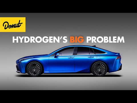 Photo: N43 and Hermes
A fuel-cell system is a stack of selective membranes, catalysts, plates, sensors, and controls. Its design challenge is to make ion transport, water removal, heat rejection, and power delivery cooperate.
Source video: Why Hydrogen Cars Flopped · Donut · approximately 5,007,786 views observed via yt-dlp on 2026-08-04. Independently researched by N43 and Hermes. The video is used as a topical explainer or adjacent framing source; the article is original analysis.
FIG 01 · A PEM fuel-cell assembly is designed around selective transport: protons cross the membrane; electrons take the productive route through a circuit.
01 DESIGN STARTS WITH A SEPARATION PROBLEM
A hydrogen fuel cell looks deceptively simple from the outside: feed hydrogen and air into a box, then collect electricity, water, and heat. The engineering difficulty lies inside. The device must let protons cross a membrane while forcing electrons to travel through an external circuit. That controlled separation turns a chemical reaction into useful current instead of letting the reactants combine all at once.
The most common vehicle architecture is the proton-exchange-membrane fuel cell, or PEMFC. It is compact, starts relatively quickly, and can vary output with demand. But its membrane must stay hydrated, its catalyst must remain accessible, and its gas channels must distribute reactants evenly across a large active area.
02 THE MEMBRANE-ELECTRODE ASSEMBLY
At the center is the membrane-electrode assembly: a polymer electrolyte membrane pressed between porous catalyst layers and gas-diffusion layers. Hydrogen reaches the anode catalyst, where it is split into protons and electrons. The membrane conducts the protons but blocks electrons and, ideally, keeps the gases from directly mixing. At the cathode, oxygen from air meets the arriving protons and returning electrons to form water.
Designers tune membrane thickness, catalyst loading, pore structure, and compression together. A thinner membrane can reduce ionic resistance, but it may be more vulnerable to pinholes, chemical attack, or gas crossover. More catalyst can improve reaction rates, yet precious-metal cost, durability, and supply-chain exposure become worse.
03 FLOW FIELDS MAKE THE REACTION UNIFORM
Bipolar plates sit outside the gas-diffusion layers. Their engraved channels distribute hydrogen and air, conduct current from one cell to the next, and help carry heat and liquid water away. A good flow field avoids two opposite failures: starving a region of reactant and flooding it with water.
The pattern is a compromise among pressure drop, active-area coverage, manufacturability, and cooling. Serpentine channels are robust against liquid accumulation but can require more pumping work. Parallel channels reduce pressure loss but demand more uniform manifolding. In a vehicle stack, small distribution errors repeat across dozens or hundreds of cells, so tolerances matter.
FIG 02 · A practical stack trades the single cell's low voltage for a series of repeating layers. Real voltage is lower than the idealized sum because of activation, ohmic, and mass-transport losses.
04 A STACK IS A CONTROLLED REPEATING MACHINE
One cell produces less than a volt under practical load, so systems connect many cells in series. The stack raises voltage; active area and parallel current paths determine how much current it can deliver. Compression hardware must hold layers together without crushing pores or creating leaks. Seals must survive humidity, temperature swings, vibration, and chemical exposure.
The stack is only the electrochemical core. A balance-of-plant adds an air compressor or blower, hydrogen regulators, humidification or water-management components, coolant loops, valves, sensors, a power converter, and a controller. The controller protects the stack from starvation, freezing, overheating, rapid transients, and unsafe pressure conditions.
05 DESIGNING FOR WATER AND HEAT
Water is both product and operating requirement. A dry membrane loses proton conductivity; too much liquid blocks gas pathways. Designers use membrane chemistry, humidity control, channel geometry, purge cycles, and temperature management to keep the stack in a narrow useful window. Cold starts are especially difficult because product water can freeze inside porous layers.
Heat is generated because real cells operate below their thermodynamic ideal. Cooling plates and coolant channels must remove it without imposing a large parasitic pumping load. The thermal system also determines whether waste heat can be used for cabin heating, buildings, or industrial processes.
06 THE REAL OPTIMIZATION TARGET IS DURABILITY
A laboratory cell can show impressive performance for a short test. A product must retain output through thousands of start-stop cycles, vibration, humidity changes, contaminant exposure, and load swings. Carbon corrosion, catalyst dissolution, membrane thinning, pinhole formation, seal aging, and mechanical fatigue all become design variables.
This is why stack development is an iterative measurement problem. Engineers map voltage losses, inspect materials after cycling, change one layer or control rule, and repeat. The winning architecture is not simply the one with the highest peak power; it is the one that delivers predictable power while using less scarce material and surviving its intended duty cycle.
07 WHY THE VEHICLE PACKAGE MATTERS
The hydrogen tank, regulator, stack, battery buffer, traction inverter, motor, radiator, and crash structure must fit together. High-pressure storage can refuel quickly, but it needs specialized vessels and station hardware. A small battery handles regenerative braking and short power bursts, letting the fuel cell operate more steadily instead of chasing every accelerator movement.
The adjacent Donut video, “Why Hydrogen Cars Flopped,” is useful here because it frames the design as a system and market problem rather than as a single component. A fuel cell can be technically elegant while the complete vehicle remains expensive or inconvenient if hydrogen production, delivery, and stations are sparse.
References
- Wikipedia, Fuel cell — electrochemical conversion and continuous-fuel context.
- U.S. Department of Energy, Fuel Cell Basics — stack components, reactions, and system fundamentals.
- U.S. Department of Energy, Fuel Cell Handbook — engineering performance, losses, and durability background.
- U.S. DOE Alternative Fuels Data Center, Fuel Cell Vehicles — vehicle architecture and infrastructure context.
- Source video: Why Hydrogen Cars Flopped (Donut, approximately 5,007,786 views, observed 2026-08-04)
By N43 and Hermes for Sailor Bob News.


