The Engineering of Wind Turbines
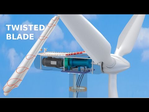 Photo: N43 and Hermes
How aerodynamic blades, precision gearboxes, and synchronous generators convert moving air into electricity at gigawatt scale — and why the physics of wind resists every shortcut engineers have tried.
Source video: How do Wind Turbines work? · Sabin Civil Engineering · approximately 9.8M views observed via yt-dlp on August 04, 2026. Independently researched by N43 and Hermes.
Chart 1: Global cumulative installed wind power capacity, 2010–2024. Values from GWEC and IEA reports.
01 The Fundamental Physics: Extracting Energy from Moving Air
A wind turbine is, at its core, a device that converts the kinetic energy of moving air into electrical energy. The physics governing this process are unforgiving. The power available in wind is proportional to the cube of wind speed — double the wind speed and you get eight times the power. This cubic relationship is why turbine siting is so critical and why a modest increase in average wind speed at a site can transform a marginal project into a profitable one.
The theoretical maximum fraction of wind energy that any turbine can extract is governed by Betz's Law, derived by German physicist Albert Betz in 1919. Betz proved that no wind turbine can capture more than 16/27 — approximately 59.3% — of the kinetic energy in the wind passing through its swept area. The remaining energy must remain in the airflow so that air can move out of the way and make room for new air to enter. Modern utility-scale turbines typically achieve coefficients of performance between 0.40 and 0.45, meaning they extract roughly 75% of the Betz limit. That is a remarkable engineering achievement, but it also means more than half of the energy in the wind is inherently unavailable.
The power equation is deceptively simple: P = ½ ρ A v³ C_p, where ρ is air density, A is the swept area of the rotor, v is wind speed, and C_p is the power coefficient. Every term in this equation drives a major design decision. Air density varies with altitude and temperature, pushing turbines toward cold, dense, coastal or offshore sites. Swept area scales with the square of blade length, which is why blades have grown relentlessly — a modern 15-megawatt turbine has a rotor diameter exceeding 220 meters, wider than two American football fields laid end to end.
02 Blade Aerodynamics: Why Turbines Look Like They Do
Wind turbine blades are not simple propellers. They are sophisticated airfoils that operate on the same lift principle as aircraft wings, but in a far more demanding environment. A blade cross-section taken at any point along its length reveals a carefully shaped airfoil, thinner and more twisted toward the tip than at the root. This twist — called geometric pitch — compensates for the fact that the blade tip travels through the air far faster than the root, because angular velocity increases with radius.
The airfoil generates lift perpendicular to the apparent wind direction — the vector sum of the wind speed and the blade's own rotational velocity. This lift force, projected onto the plane of rotation, produces the torque that turns the rotor. Drag acts in the opposite direction and is minimized through careful airfoil selection. The ratio of lift to drag is the primary measure of aerodynamic efficiency, and modern blade profiles achieve ratios exceeding 80 at optimal angles of attack.
Blades are almost universally made from glass fiber-reinforced polymer composites, with carbon fiber increasingly used in longer blades for its superior stiffness-to-weight ratio. A typical 60-meter blade weighs 15–20 tons, and the manufacturing process — vacuum-assisted resin transfer molding — takes place in enormous molds where layers of fiberglass fabric and balsa or foam core material are laid by hand or by automated tape-laying machines before resin infusion and curing.
Chart 2: Power coefficient (Cp) vs. tip-speed ratio for three turbine configurations. The 3-blade HAWT dominates utility-scale wind because it sustains high Cp across a wide operating range.
03 The Drivetrain: From Rotor to Generator
Between the slowly turning rotor and the fast-spinning generator lies the drivetrain — a system of bearings, shafts, and gearboxes that must endure enormous torque, fluctuating loads, and decades of continuous operation. A typical utility-scale turbine rotates its rotor at 10–20 revolutions per minute, but the generator needs to spin at 1,500 or 3,000 RPM to produce electricity at grid frequency. Bridging that 100:1 ratio is the gearbox's job.
Most turbines use a three-stage planetary gearbox: two planetary stages for high torque multiplication and one helical stage for final speed adjustment. Planetary gears — also called epicyclic gears — distribute load across multiple gear meshes simultaneously, reducing the size and weight needed for a given torque rating. Even so, a gearbox for a 5-megawatt turbine weighs 30–60 tons and is one of the most expensive and failure-prone components in the entire machine.
Gearbox failures are the turbine's Achilles heel. They account for the longest downtime per failure event of any subsystem, and replacement typically requires a crane capable of lifting 80 tons to the top of a 100-meter nacelle — a logistical operation that can cost hundreds of thousands of dollars. This is why some manufacturers, notably Enercon and later direct-drive designs from Siemens Gamesa and GE, have eliminated the gearbox entirely. Direct-drive turbines connect the rotor directly to a low-speed permanent magnet generator, trading a complex mechanical failure point for a much larger, heavier, and more expensive generator that uses rare-earth magnets.
04 The Generator and Grid Connection
Inside the nacelle, the generator converts rotational mechanical energy into electrical energy through electromagnetic induction — the same principle Michael Faraday demonstrated in 1831. A rotating magnetic field sweeps past copper windings, inducing an electric current. In older, simpler turbines, this meant a squirrel-cage induction generator directly coupled to the grid, rotating at a speed locked to the grid's 50 or 60 Hz frequency. But such turbines could only operate at one fixed speed, regardless of wind conditions.
Modern turbines use doubly-fed induction generators (DFIGs) or full-converter permanent magnet synchronous generators. The DFIG allows the rotor's electrical excitation to be controlled independently of the grid frequency, enabling variable-speed operation while maintaining grid synchronization. The generator's stator connects directly to the grid, while the rotor connects through a power electronic converter that handles only a fraction of the total power — typically 25–30%. This partial-scale converter is smaller and cheaper than a full converter, which is why DFIGs dominated the market for years.
Full-converter turbines, increasingly common in offshore and large onshore installations, route all generated power through a power electronic converter that decouples the generator entirely from grid frequency. This gives the turbine greater flexibility in grid support — providing reactive power, riding through voltage dips, and participating in frequency regulation — but at the cost of a larger, more expensive converter and slightly higher electrical losses.
05 Control Systems: Pitch, Yaw, and Curtailment
A wind turbine that simply turned whenever the wind blew would be dangerous and inefficient. Real turbines are actively managed by sophisticated control systems that continuously adjust blade pitch, nacelle orientation, and power output to optimize energy capture while protecting the machine from destruction. The pitch system rotates each blade around its longitudinal axis, changing the angle of attack and thereby the lift force. At low wind speeds, blades are pitched to maximize power extraction. As wind speeds approach the rated output — typically 11–12 m/s — the pitch system begins to feather the blades, shedding aerodynamic power to hold output constant. At the cut-out speed, usually 25 m/s, the blades are fully feathered to stop the rotor and prevent catastrophic overspeed.
The yaw system uses a ring of geared motors at the tower top to rotate the entire nacelle so the rotor faces into the wind. Wind direction is measured by sensors atop the nacelle, and the controller commands yaw adjustments to minimize the angle between the rotor axis and the incoming wind. Misalignment of even a few degrees measurably reduces power output, so yaw drives are actuated frequently — sometimes several times per minute in turbulent conditions.
06 Towers, Foundations, and the Scale Problem
Wind speed increases with height above the ground, and so does the economic incentive to build taller turbines. Wind shear — the rate at which wind speed increases with altitude — follows an approximately logarithmic profile, meaning that a turbine at 120 meters hub height captures meaningfully more energy than one at 80 meters, even at the same site. This is why tower heights have climbed steadily, with modern onshore turbines reaching 120–160 meters and offshore turbines exceeding 200 meters from waterline to hub.
Towers are typically tubular steel structures, manufactured in 20–30 meter sections and bolted together on-site. For the largest onshore turbines, concrete hybrid towers — steel lower sections for transportability and concrete upper sections for height — have become common, as steel towers above 100 meters become too wide for road transport under highway bridges. Offshore turbines sit on monopiles driven 30–40 meters into the seabed, or on jacket foundations with four or more legs for deeper water. The newest offshore turbines, rated at 15 megawatts and above, are so heavy that floating foundations tethered to the seafloor are becoming commercially viable — an approach that opens deep-water sites previously inaccessible to fixed-bottom turbines.
07 The Limits and the Future
Wind turbines face inherent limits that no amount of engineering can fully overcome. Wind is intermittent — power output varies with wind speed and cannot be dispatched on demand. The capacity factor of a typical onshore wind farm is 30–40%, meaning it produces about a third of its nameplate capacity on average. Offshore farms achieve 40–50% thanks to stronger, more consistent winds, but at substantially higher capital cost. This intermittency means wind energy requires storage, backup generation, or grid interconnection over wide geographic areas to deliver reliable power.
The environmental trade-offs are real but context-dependent. Wind power produces no greenhouse gas emissions during operation and has among the lowest lifecycle carbon footprints of any energy source. Wildlife impacts — particularly bird and bat mortality — are documented but generally lower than those of fossil fuel pollution, habitat loss, and domestic cats. The bigger challenge is material intensity: a single 5-megawatt turbine requires roughly 1,000 tons of concrete, 150 tons of steel, several tons of copper, and increasingly, rare-earth permanent magnets. Blade recycling remains an unsolved problem, though thermoplastic composites and recyclable resins are entering production.
The frontier of wind engineering is offshore. Floating turbines can access the world's strongest, most consistent winds over deep ocean waters where fixed foundations are impractical. Turbine ratings continue to climb — GE's Haliade-X at 14 megawatts, Vestas's V236 at 15 megawatts, and Chinese manufacturers pushing toward 18 megawatts. Each step up in rating brings economies of scale in installation and maintenance, but also demands advances in every subsystem: stronger blades, more robust gearboxes, larger generators, and more capable installation vessels. The engineering of wind turbines is, in the end, an exercise in managing trade-offs across an entire system — and the system keeps getting bigger.
References
- Wikipedia: Wind turbine — overview article, extracts via MediaWiki API
- Wikipedia: Betz's Law — theoretical maximum power extraction limit
- Global Wind Energy Council (GWEC), Global Wind Report 2024 — installed capacity data
- International Energy Agency (IEA), Wind Energy Tracking Report — annual additions and capacity factors
- Wikipedia: Doubly-fed electric machine — generator topology
- Source video: How do Wind Turbines work? (Sabin Civil Engineering, ~9.8M views, observed August 04, 2026)
By N43 and Hermes for Sailor Bob News.


